Foam Assisted Lift Technology to Improve Recovery Factor
| ✅ Paper Type: Free Essay | ✅ Subject: Engineering |
| ✅ Wordcount: 2699 words | ✅ Published: 30 Aug 2017 |
PROCEEDINGS, INDONESIAN PETROLEUM ASSOCIATION
Forty first Annual Convention & Exhibition, May 2017
Foam Assisted Lift Technology to Improve Recovery Factor from Sensitive Wells, lesson learned from Total E&P Indonesie
Ramot Sianturi*
Jodi Astorifa Anggoro*
Muhammad Nadrul Jamal*
Chiko Eko Jatmiko*
ABSTRACT
Total E&P Indonesie (TEPI) currently produce ±1600 MMSCFD of gas from 5 major gas fields, which are Tunu, Sisi-Nubi, South Mahakam, Peciko and Tambora. Except South Mahakam and Sisi-Nubi, all other fields are mature and already in declining production. On some very sensitive gas wells, there have been liquid loading problem observed, a phenomena of inability to continuously lift liquid from borehole. The accumulated liquid increases hydrostatic pressure and eventually stop the well production.
 As a solution, TEPI introduced a “Foam Assisted Lift (FAL)” technology in 2011 as a pilot phase, and continued in 2012-2013 on more wells part of FAL trials. The principle of FAL is to generate bubbles to reduce hydrostatic pressure, through surfactant injection from surface to down-hole using capillary string (CS) set under specific well intervention arrangement. Starting from the pilot phase, TEPI have performed several improvements and development of robust down-hole equipments, operation, and also the selection criteria of candidate wells.
During several phases of FAL pilots, TEPI had defined the selection method and criteria of good FAL candidates; good productivity (defined as Porosity x Net pay thickness), good offload response, condensate and liquid ratio less than 60%, and bottom hole shut in pressure higher than 1000 psi. The new selection criteria was fully implemented in 2015 campaign, and resulted in improved production in 10 wells. FAL is considered as proven technology to maintain production stability of very sensitive gas wells.
Keywords: Capillary string, liquid loading, foam assisted lift, selection criteria
INTRODUCTION
Total E&P Indonesia (TEPI) produces ±1600 MMscfd in 2016, it was decreasing sharply from 2010 which could produced ±2000 MMscfd. One of the main challenges to maintain the plateau production of TEPI is the liquid loading issue which means the inability to lift liquid out from gas wells. This liquid loading issue triggers to self killing process as shown in Figure 1. In the beginning of well’s life, well produced in high gas rate and relatively dry. Through the time gas production decreases, water starts to be produced and less energy to lift the liquid. As the consequence, liquid will start to be accumulated in the borehole then eventually stop the well production.
Liquid loading issue would always happened in gas wells, it just only the matter of time. To minimize and longer well’s life, until recently TEPI performs regular offload by decreasing Well Head Flowing Pressure (WHFP) close to atmospheric pressure and flaring, involving substantial means such as testing barge and personnel. These offloading activities present specific risks, not only for safety, personnel, and assets, but also impact in environment from the flaring activity which results in Green House Gas (GHG) emissions. Moreover, this offloading is only temporary solution to boost the production. Therefore, a continuous offloading system is required to maintain the sustainability of production. Several technologies for continuous offloading are shown in Table 1.
Based on Table 1, the most possible technology to be applied is Foam Assisted Lift (FAL) through CS considering no energy required, comply with company rules, and less cost compare to others. Principal of FAL is by creating foam at down-hole to reduce the hydrostatic pressure at wellbore in order to help the lifting of liquid to surface. The process sequence of FAL is shown in Figure 2;
- Addition of surfactant inside the well will reduce gas-liquid surface tension
- The reduction of surface tension will impact to the reduction of liquid density
- Hydrostatic pressure will be reduce as the impact of lighter liquid’s density
- Reduction of hydrostatic pressure will give more drawdown, delta pressure between reservoir pressure and bottom hole flowing pressure (BHFP)
- Additional drawdown will give more gas rate production
Technology FAL has been developed in TEPI in 2011 as a pilot phase and continued in 2012-2013 on more wells as part of FAL trials. Starting from the pilot phase, TEPI have performed several improvements and development of robust down-hole equipments, operations, and also the criteria of candidate selection.
CAPILLARY STRING INJECTION SYSTEM
Down-hole Equipment
CS down-hole system is an additional tubing (injection system) that inserted inside production tubing. Even though additional CS inserted inside, TEPI still complies and respects to safety by keeping down-hole safety valve (DHSV) installed. It is mandatory to equip subsurface safety valve in onshore and offshore wells in TEPI for safety purpose as second barrier if any damage or malfunction of surface system happened. Initially the DHSV opening and closing is controlled by hydraulic pressure from control panel but after equipped with CS down-hole system, the opening and closing is controlled by surfactant pressure from surface surfactant facilities.

DHSV in CS well is inserted or incorporated in a Weatherford Injection and Safety Hanger (WISH). The WISH hanger also locks the CS tubing, top and injection valve, and dual check valves as shown in the Figure 3. Dual check valves are used at top and bottom injection valve to prevent well pressure from production tubing entering the system in CS tubing and DHSV control line. Besides that, the purpose of dual check valves also to prevent reverse flow of surfactant or fluid s from wells which is potentially could cause plugging. Top injection valve installed immediately after WISH with purpose to pressurize and open DHSV at certain cracking pressure (±2000 psi) then it will allow surfactant to flow to bottom part of CS tubing. Bottom injection valve is installed at the bottom part of the tubing with purpose to inject surfactant inside production tubing.
Surface Facilities
Surface facilities were designed to allow the surfactant injection from surface to wellbore with consideration to safety aspect, production reliability, and production availability. Whole surface facilities in CS well are shown in the Figure 4. CS surface facilities consist of several equipments as follow:
- Surfactant tank; Tank that used shall be made from metallic tank since based on MSDS, surfactant is consider as flammable fluid.
- Pump; Surfactant injection pump’s type is positive displacement driven by instrument gas. In the earlier phase, installed pump is only one but due to the frequency of pump’s failure, it is decided to install dual pump with philosophy one in operation and one as back-up.
- Pressure Switch High-High (PSHH); PSHH is installed to protect the equipment from overpressure due to blocked outlet discharge of surfactant injection line or reverse flow from reservoir.
- Pressure Switch Low-Low (PSLL); PSLL is installed to identify any leak/ rupture in the injection line or to identify if the pump stop working that could lead to pump cavitations.
- Pressure Safety Valve (PSV); PSV is installed at discharge line of pump to protect the surface facilities
Surfactant
Criteria that shall be considered during surfactant selection process are the foam efficiency and stability. Several laboratory tests have been performed to check and validate these two criteria. Qualifications of surfactant that been used in TEPI are as follow:
- The product could be used high temperature environmental ( ±1760C) since it would be injected up to wellbore
- No plugging issue cause by surfactant if injection stopped
- Compatible with other chemicals that injected in the flow-line, i.e corrosion inhibitor
CANDIDATE SELECTION
In the early phase on 2011, candidate of CS wells were selected based on the well’s behavior (stable or intermittent flow), offload frequency, turner rate, and response to shut in for pressure build up (SIBU). The preliminary step for candidate selection is the well’s behavior review before going in to deeper to the other criteria. A well that suffered with liquid loading could be identified by increasing of water production rate, and then followed by sudden decrease of gas production rate and decreasing of liquid lifted to surface that corresponding to the critical/ turner rate reached. The trend of WHFT also gives a good sign to do preliminary selection.
Case 1 – Well with Low Productivity and Low Gas Rate during offload
Figure 5 is one of CS well’s production evolution profile that selected based on the selection criteria above. As shown in the graph, the well still gave response to the offload that performed on October 2012 with high water production, ±700 bwpd but in limited gas rate, ±0.5 MMSCFD. This well clearly shown outflow problem as describes on liquid level column inside well based on pressure and temperature survey that given on Figure 6.
CS was installed on May 2013, but there was no significant improvement in gas production even it was clearly confirmed that the well has issue in liquid lifting. Existence of water and response to offload could not ensure the successful of FAL, cut off of gas rate required to ensure the agitation and mixing between liquid and gas needs to be defined as well. Besides that, the productivity of the well needs to be checked as well. As shown in the IPR and VLP curve, well with higher productivity will give higher gain in any changes on VLP shape.
Case 2 – Well with Higher Condensate Liquid Ratio
Figure 7 is sample of CS well that have high condensate ratio in liquid, ±80% of condensate in liquid. Based on the graph, gas rate production since October 2012 shown decreasing trend but still responsive to SIBU and offload (Qgas rate offload on August 2013 gave value ±1.5 MMSCFD). Considering the initial selection criteria, this well was a good candidate for CS, but after installed with CS, there was no significant improvement. Unsuccessful result potentially caused by the existence of high condensate rate. Since surfactant that used as FAL is water base, it would create foam if only water exist in the certain composition. If liquid consist more condensate, foam will not be created and the impact potentially will give additional back pressure to the well itself.
Case 3 – Well with Low Bottom Hole Shut In Pressure (BHSIP)
Well in Figure 8 was installed with CS since August 2013. As shown in the graph, even though the well shown positive response in offload (Qgas rate at ±3 MMSCFD) and mainly produced water instead of condensate, the result after CS installation did not show positive improvement. Reviewing further from reservoir point of view, this well indicated a good productivity but the pressure (BHSIP) has been at low value.
Based on the result on CS wells that selected based on criteria above (conventional approach), found that criteria above were still not capable enough to give higher success ratio. As in cases above, several parameters should be included in the selection process, such as productivity, response to offload, condensate liquid ratio, and BHSIP. Statistical approach has been performed to define the new selection that could give higher success ratio. Based on the review, parameters or criteria that could improve the success ratio are as follow:
- Productivity
As shown in the Figure 5, more gain could be reached in the high productivity wells. The unloading of well with FAL through CS would give additional drawdown in front of the reservoirs. In the same drawdown, the higher gain would be given by the well with higher productivity. In TEPI, the productivity is represented by the height multiply with the porosity. The higher the height and porosity, the higher would be the productivity. In order to improve the success ratio of CS wells, TEPI implemented the cut-off productivity at value 250.
- Response to Offload
FAL by surfactant does not bring any additional energy to the system. The well itself should be able to revive by itself in order to activate the foaming effect efficiently and effectively. Therefore, response to the offload is important to confirm CS candidate prior the installation. Good candidate for CS shall have an improvement in gas rate and liquid production at atmospheric pressure compared to LP. Based on review in existing CS wells, cut-off value to confirm candidate CS that implemented in TEPI is 1.3 MMSCFD in offload condition.
- Condensate liquid ratio
Condensate is natural killer of foam. It would collapse the existence of foam. Based on laboratory test, minimum of 40% water in the liquid is still sufficient to create effective and stable foam. Therefore, the ratio of condensate and water needs to be considered as well during the selection candidate process.
- BHSIP
BHSIP value could be used to represent reservoir pressure. Therefore, candidate for CS wells shall still have high BHSIP, it would not be too depleted reservoirs. Even though BHISP is used as one of the criteria, needs to be careful in the selection process since higher BHSIP could be also due to higher liquid column.
Case 4 – Well that Selected Based on New Selection Criteria
New selection criteria that are included the cut-off productivity, gas rate during offload, condensate liquid ratio, and BHSIP have been fully implemented in 2015. TN-H13 is one of CS well that already selected based on this selection criteria.
- Productivity that represents by the value of height multiply with porosity is ±460 meanwhile the cut-off is at 250
- Last offload that performed on August 2013 still gave value at 2.6 MMSCFD meanwhile the cut-off is at 1.3 MMSCFD
- Condensate ratio was at ±34% before CS installed meanwhile the cut-off is at 60%
- BHSIP based on pressure and temperature monitoring is at 1600 psi meanwhile the cut-off is at 1000 psi
As shown in Figure 9, Production trend from point A (February 2014) to point B (May 2014) shown decreasing trend and limited water lifted to surface. In the end of May 2014, after reviewed based on new selection criteria, well gave significant improvement in gas rate after installed with CS. Gas production from point B (±0.7 MMSCFD) increase to point C (±2.5 MMSCFD) and then gave stable production. Good response to the FAL technology also given by the increasing of water rate that could lifted to surface.
These new selection criteria have been fully implemented in 15 wells along 2015 and gave production improvement in 10 wells.
DOWNHOLE MEMORY GAUGE
As part of learning process, beside define the new selection criteria, the impact of surfactant injection rate on reduction of BHFP needs to be evaluated as well. The method to evaluate this BHFP reduction is by installing memory gauge at the edge of CS tubing. Total memory gauges installed are 5.
TN-H13 is selected based on the new selection criteria and it gave positive result in gas production after installed with CS. Positive impact on the gas production could be explained in Figure 10.
- Performed test was by varying the injection rate through several periods. It was started with low injection rate to maximum injection rate. Stabilization period was given each time injection rate changed. The purpose of stabilization period is to have same baseline in each step of injection rate.
- Increasing of injection rate gave inline result with increasing pressure reduction of BHFP.
- At the end of the trial, surfactant injection was stopped in order to see the impact in pressure reduction of BHFP. From Figure 10, it is clearly shown that by stopping surfactant injection, BHFP would be back to initial value. Therefore, it could be concluded that the addition of surfactant obviously gives positive response to production improvement.
- The addition of CS gave reduction of BHFP by 160 – 275 psi, which means additional drawdown is given to the well that will impact to additional gas rate.
CONCLUSIONS
- Fully implementation of new selection criteria (productivity, response to offload, condensate liquid ratio, and BHSIP) are applied in 2015 campaign. It is confirmed that the implementation could improved production in more than 10 wells.
- Surfactant injection inside the well that suffered with liquid is confirmed could give additional drawdown that impact to the addition of gas rate production as confirmed from memory gauge installation result.
- FAL is considered as proven technology to maintain production stability of very sensitive gas wells.
ACKNOWLEDGEMENTS
The authors gratefully acknowledge permission from SKK MIGAS, INPEX, and TOTAL to publish this paper. Our biggest gratitude is also gives to all parties who provided valuable comments and inputs during the preparation of this paper.
REFERENCE
Lea, James, Henry Nickens, and Mike Wells. (2008). Gas Well Deliquification. 2nd Edition. Gulf Professional Publishing.
Table 1. Dewatering Technologies
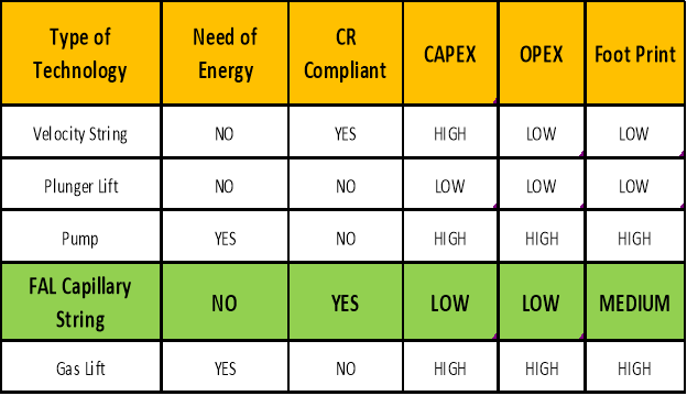
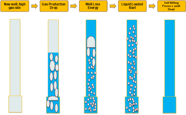
Figure 1. Liquid Loading Phenomena in Gas Wells
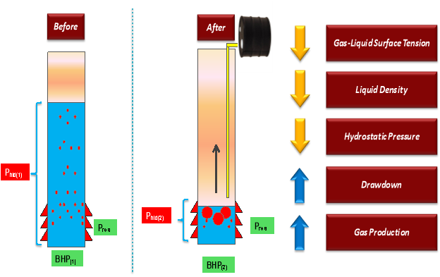
Figure 2. Process Sequence of FAL
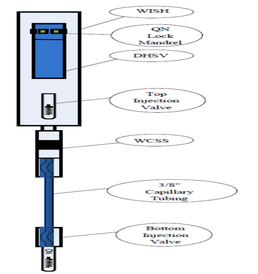
Figure 3. CS down-hole configuration
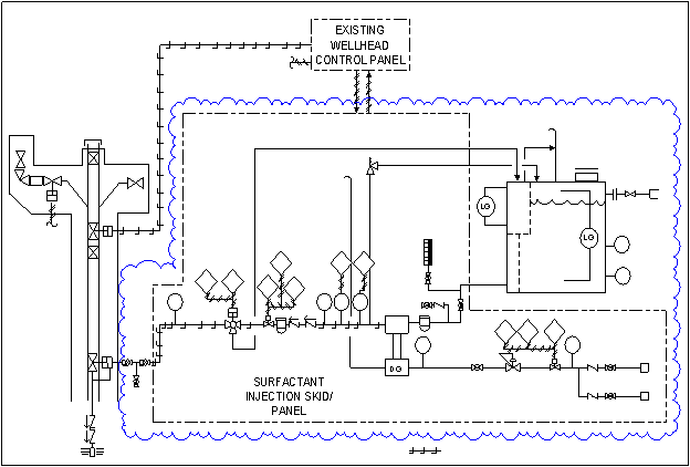
Figure 4. Process Flow Diagram and Emergency Shut Down (ESD) system
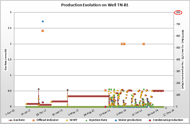
Figure 5. Production Evolution of TN-B1
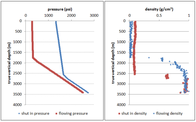
Figure 6. Gradient Pressure in Shut in and Flowing Phase of TN-B1
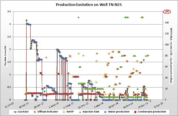
Figure 7. Production Evolution of TN-N25
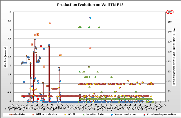
Figure 8. Production Evolution of TN-P13
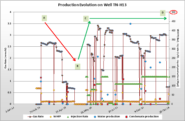
Figure 9. Production Evolution of TN-H13
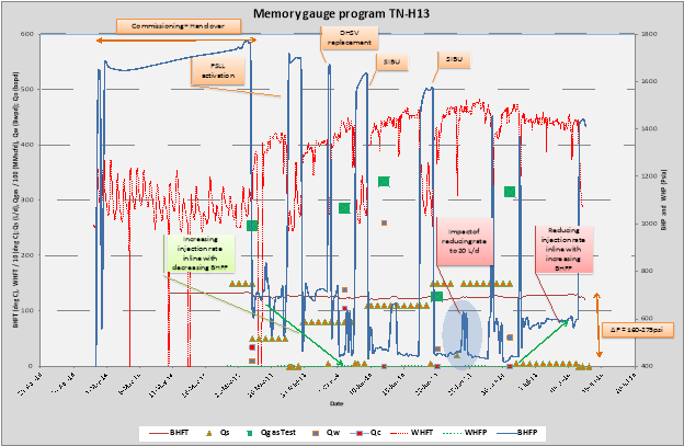
Figure 10. Memory Gauge Result of TN-H13
Cite This Work
To export a reference to this article please select a referencing stye below:
Related Services
View all


DMCA / Removal Request
If you are the original writer of this essay and no longer wish to have your work published on UKEssays.com then please click the following link to email our support team:
Request essay removal